Savox
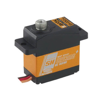
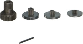
Savox Micro Size Digital Servo 3.9Kg@6V Heli & Parkfly SAV-SH0255MG+ Metal Gears
- SKU:
- SAV-SH0255MG+
- UPC:
- 4710006994192
Description
Additional Information - All Savox servos use 25t servo horns.
SAVOX MICRO SIZE DIGITAL SERVO 3.9KG@6V (HELI & PARKFLY) SAV-SH0255MG+
Micro size digital servo with refined design that brings out extraordinary performance.
Ideal for CCPM and Rudder on 450 level heli and Park Fly Airplane.
Savox SH0255MG+ Servo Features:
- Over-spec refined design overturns output limitation of ordinary micro size servo.
- The metallic body design not only exudes an exquisite style but helps the operating to stay cool and smooth from th beginning to the end.
- Production and quality control of plastic component in our servos follow the standard of branded digital camera.
- Professional and exquisite design and made gears form as the solid framework of our servos.
- Design will make "Crumbled Gear" history.
Spec Check:
- Dimensions: 22.8 x 12 x 29.4mm
- Weight: 15.8g**
- Speed (sec/60degrees): 0.13
- Torque (kg-cm/oz-in): 3.9/54.1
- Gear: Metal
- Case: Aluminium
**Weight listed does not include wires or horns.
- Operating Temperature: 14degrees - 122degreesF (-10degrees - 50degreesC)
- Running Current (no load): 180mA @4.8V, 240mA @6.0V
- Stall Current (at locked): 1200mA @4.8V, 1400mA @6.0V
- Idle Current: 5mA @4.8V, 5mA @6.0V
- Wire Length: 250 ± 5mm
- Output Gear Spline: 21 Tooth
- Bearings: 1BB
- Operating Travel: 90degrees (1000 - 2000 microns second)
- Neutral Position: 1500 microns second
- Pulse Width Range: 750 - 2250 microns second
- Maximum Travel: Appx 145degrees (750 - 2250 microns second)
- Refresh Rate: 240 Hz
- Motor Type: Brushed
Need help choosing the correct servo. Here is a handy TOOL and extra informatino below.
CHOOSING THE CORRECT SERVO - FAQ
Size - What space do I have? The size of the modal and the servo mounting dimensions can dictate the servo that you choose. There are a few different footprint classes (JUMBO, STANDARD, MINI and MICRO) and depths so there should be a servo to fit your needs.
Torque - What is the size and weight of the control surface that you are moving? The bigger and heavier the control surface on the model, the higher the servo torque needed. What is the length of the servo I am using? The longer the servo arm used the higher the servo torque needs to be to compensate.
Speed - Do you require a very fast response to make frequent corrections or have instantaneous throttle response? A fast or slow servo will alter the 'feel', it's similar to having positive or negative exponential set on your transmitter.
Voltage - What battery voltage are you using? All servos can be used with 6 volt DC supply. If you want to use the newest 2S LiPo receiver batteries you will need to choose the 7.4volt compatible servos. These servos can also be used with lower voltages but the performance will be lower.
Gear Train Material - Is this a large or powerful model? Will the model be used aggressively or with sudden high impact/energy loading? Metal gears should be used if your answer is yes. The gears are high-precision Taiwan-made aluminium with hard anodizing. For lower power less aggressive model use; or where super-lightweight is required for models, then industrial plastic gears are the perfect choice. Remember, if in doubt use metal gears.
Motor - Is the model subject to high vibration requiring fast response? Most of the range uses Coreless technology which offers a reliable and powerful motor, this is the gold standard. Brushless motors give the platinum standard, resulting in ultimate power, quicker torque, faster response, greater efficiency and incredibly durable.
Bearings - Is the model used in a high vibration environment? Most servos use a double ball race on the output shaft to ensure long life, accurate control and improved resolution. Twin ball race is the best on larger, higher vibration and powerful models. A single ball race is suitable for lightweight, low vibration and smaller models.
Servo Case Material - Will the servo be moving from endpoint to endpoint and used aggressively? Aluminium is used to improve heat dissipation from the motor but this has a slightly higher weight over the plastic case models. A full aluminium case also provides a more stable platform for the gear trains and mounting points and is used in larger scale models.
Weight - Where is the servo mounted? Will the weight of the servo have an effect on the performance of the model? Choose the lightest servo or move a heavier servos position to reduce the effect on the model. Remember, you can save weight by using aluminium arms and titanium turnbuckles.
Servos from the outside
From the outside, the servo has a few basic parts:
- Case
- Mounting tabs
- Output shaft
- Servo horn
- Cable
- Connector
Let us consider each of the parts in a bit more detail.
1. Case
The case holds together most of the servo and protects its internal components. The case is usually made of three plastic sections screwed together, but some really small servos might only be held together by heat shrink or stickers. In some fancy servos, the middle section of the case is made of metal for better heat dissipation to keep high-performance motors and electronics from overheating. Some servos are better sealed than others for moisture protection with extra gaskets or O-rings between the case segments and on the screws. In the picture to the right, the top of the case is removed, showing the blue O-ring between the top segment and middle segment.2. Mounting tabs
The mounting tabs are molded into the case, but I am listing them separately because of their distinct function. In a typical installation into a sheet of material, a rectangular hole that is big enough for the case but smaller than the tabs is cut out; the tabs can then be screwed down to the sheet. Many servos are supplied with a small bag of hardware including screws and grommets for mounting the servo with some shock or vibration protection. Since the mounting tabs do not involve the workings of the servo, they can be cut off for space-constrained installations. Servos, especially small ones, are often mounted with double-sided tape or cable ties.
3. Output shaft
The output shaft is usually not visible until we take off the servo horn; here are the same servos as before with the horns removed:
The output shafts have splines, little grooves along the shaft, and screw holes for securely mounting servo horns without any slipping. Servo output shafts are generally not standardized: different servo sizes require different outputs, and even within standard-size servos, different manufacturers use different splines that are incompatible with each other. If you ever need to count the splines, a digital camera can function as a good magnifying glass or microscope: it’s much easier to take a picture, zoom in on your screen, and count the splines than to try to count them directly on the servo.
4. Servo horns
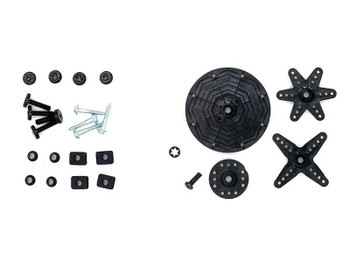
Servo horns are attachments that fit over the output shaft that allow you to mechanically link the servo output to the rest of your mechanism. Servos are usually supplied with an assortment of servo horns:
Unfortunately, the exact horns included are usually not specified and can vary. And, since servo output shafts and their splines vary, horns are often incompatible between brands and models of servo. Various specialty horns, for instance extra large ones and metal ones, are available from some servo manufacturers or as aftermarket accessories. Another type of specialty horn is the "servo saver", which has an integrated spring to limit shocks transmitted from the external mechanism to the servo.
5. Cable
Servos have three-wire cables that supply power and commands to servos. The cables are typically six to twelve inches long, with 22 gauge and thinner wires (smaller servos tend to have shorter and thinner wires). Since the connectors have become more standardized, the order of the wires has also become standardized, with the power wire in the middle flanked by ground and signal wires. However, the color schemes still vary. Common ones are:
- Black for ground, red for power, white for signal
- Brown for ground, red for power, and orange for signal
- Black for ground, red for power, blue for signal
My preference is for the first scheme since that offers the most contrast; the orange and brown of the second scheme can look kind of similar with bad lighting, as can the blue and black of the third approach. You are almost guaranteed to instantly destroy a servo if you connect power backwards, so make sure you double-check your connections.
6. Connector
The three-conductor cable is terminated with a 3-pin connector, which is almost universally a female connector with 0.1"" spacing. Unfortunately, much of the RC world calls this female connector a male connector. As with the cable colors, the connector colors can vary. The "Futaba" plug, on the left in the picture below, has an extra polarizing tab (on the left side in the picture) that can be cut off to match the others, which are called "JR" (center) and "Airtronics Z" (right). Some of the brand names might vary by country; the most common names I see from generic servo makers in China are "Futaba" and "JR".
Viewed from the end, the connectors have two beveled corners to help prevent plugging servos in backwards. That prevention mechanism relies on the RC receiver having a corresponding cutout, which is not present on most servo controllers and other electronics a robot builder might be using instead of the usual radio control components. Again: pay attention when plugging in your servos!
"


